Computer Architecture
In this chapter, we will create our memory, the CPU, and assemble everything into the complete Hack computer architecture which can load and execute programs!
Memory
Here is the Verilog code for the memory:
module Memory(
    input clk,
    input [14:0] address,
    input [15:0] in,
    input load,
    output [15:0] out
);

    // Declare memory arrays
    reg [15:0] RAM [0:16383];  // 16K RAM
    reg [15:0] SCREEN [0:8191]; // 8K Screen memory

    wire is_ram = (address < 15'h4000);
    wire is_screen = (address >= 15'h4000 && address < 15'h6000);
    wire is_keyboard = (address == 15'h6000);

    reg [15:0] keyboard_state;

    // Memory write operation
    always @(posedge clk) begin
        if (load) begin
            if (is_ram)
                RAM[address] <= in;
            else if (is_screen)
                SCREEN[address - 15'h4000] <= in;
        end
    end

    // Memory read operation
    assign out = is_ram ? RAM[address] :
                 is_screen ? SCREEN[address - 15'h4000] :
                 is_keyboard ? keyboard_state :
                 16'b0;

endmodule
This Memory module represents the main memory of the Hack computer. It includes:
- 16K words of RAM (0x0000 to 0x3FFF)
- 8K words of screen memory (0x4000 to 0x5FFF)
- A single word for keyboard input (0x6000)
Note, 0x means "this is a hexadecimal number" (base 16 instead of base 10). When the computer wants to store or retrieve data, it uses these addresses to know exactly where to go. The CPU can "visit" any of these addresses to read or write data, whether it's general information in the RAM, pixels on the screen, or checking what key was last pressed.
This module also supports both read and write operations, controlled by the 'load' input.
... Testing with GTKWave ...
CPU
As for any von-Neumann architecture, the CPU module is the heart of the Hack computer. It processes instructions and manages the program flow.
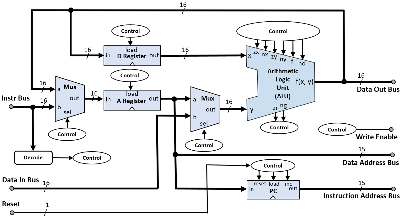 |
|---|
| Hack computer CPU block diagram created by Rleininger, CC BY-SA 4.0. |
Here is the Verilog code:
module CPU(
    input clk,
    input reset,
    input [15:0] inM,
    input [15:0] instruction,
    output [15:0] outM,
    output writeM,
    output [14:0] addressM,
    output [14:0] pc
);

    // Instruction decoding
    wire [15:0] A_Reg, D_Reg, ALU_out;
    wire [5:0] control_bits = instruction[15:10];
    wire [2:0] jump = instruction[2:0];

    // A and D registers
    reg [15:0] A, D;

    // ALU instantiation
    ALU alu(
        .x(D),
        .y(A_Reg),
        .zx(control_bits[5]), .nx(control_bits[4]),
        .zy(control_bits[3]), .ny(control_bits[2]),
        .f(control_bits[1]),  .no(control_bits[0]),
        .out(ALU_out),
        .zr(), .ng()
    );

    // A Register logic
    always @(posedge clk or posedge reset) begin
        if (reset)
            A <= 16'b0;
        else if (!instruction[15] || (instruction[15] && instruction[5]))
            A <= !instruction[15] ? instruction : ALU_out;
    end

    // D Register logic
    always @(posedge clk or posedge reset) begin
        if (reset)
            D <= 16'b0;
        else if (instruction[15] && instruction[4])
            D <= ALU_out;
    end

    // Program Counter logic
    reg [14:0] PC;
    always @(posedge clk or posedge reset) begin
        if (reset)
            PC <= 15'b0;
        else if (/* jump condition */)
            PC <= A[14:0];
        else
            PC <= PC + 1;
    end

    // Output assignments
    assign A_Reg = instruction[15] ? inM : A;
    assign outM = ALU_out;
    assign writeM = instruction[15] && instruction[3];
    assign addressM = A[14:0];
    assign pc = PC;

endmodule
It implements:
- Instruction decoding: Extracts control bits and jump conditions from the instruction.
- A and D registers: Store address and data values respectively.
- ALU: Performs arithmetic and logical operations.
- Program Counter (PC): Keeps track of the next instruction to execute.
The CPU operates in a fetch-decode-execute cycle, updating registers and memory based on the current instruction.
... Testing with GTKWave ...
Instruction Memory
The Instruction Memory module represents the ROM of the Hack computer. So it stores the program instructions and provides them to the CPU based on the address input. The $readmemb system task is used to initialize the ROM with a program file which we feed the program.hack file into:
module InstructionMemory(
    input [14:0] address,
    output reg [15:0] instruction
);

    // ROM to store instructions
    reg [15:0] ROM [0:32767];  // 32K ROM

    // Read instruction from ROM
    always @(*) begin
        instruction = ROM[address];
    end

    // Initialize ROM with program
    initial begin
        $readmemb("program.hack", ROM);
    end

endmodule
... Testing with GTKWave ...
Computer
So finally, this is our complete computer architecture which ties all the previously designed components together:
- CPU: Executes instructions and manages program flow.
- Instruction Memory: Provides instructions to the CPU.
- Data Memory: Stores and retrieves data, including I/O operations.
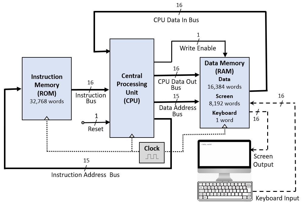 |
|---|
| Hack computer block diagram created by Rleininger, CC BY-SA 4.0. |
module Computer(
    input clk,
    input reset
);

    wire [15:0] inM, instruction, outM;
    wire [14:0] addressM, pc;
    wire writeM;

    // CPU instantiation
    CPU cpu(
        .clk(clk), .reset(reset),
        .inM(inM), .instruction(instruction),
        .outM(outM), .writeM(writeM),
        .addressM(addressM), .pc(pc)
    );

    // Instruction Memory instantiation
    InstructionMemory instr_mem(
        .address(pc),
        .instruction(instruction)
    );

    // Data Memory instantiation
    Memory data_mem(
        .clk(clk),
        .address(addressM),
        .in(outM),
        .load(writeM),
        .out(inM)
    );

endmodule
... Testing with GTKWave ? ...
As such, this module represents the complete Hack computer system. It operates by:
- Fetching instructions from Instruction Memory based on the PC.
- Executing these instructions in the CPU.
- Reading from and writing to Data Memory as needed.
- Updating the PC to move to the next instruction.
A.k.a. the von-Neumann architecture.