Boolean Arithmetic
Let's build up the individual modules which are typical for ALUs within CPUs, step-by-step. Note that the HACK architecture is extremely simplified. Compare the Verilog I show below to that of other designs and you'll quickly notice the simplicity.
Open the logic.circ Logisim file from the root directory to try out and experiment with the circuits I present here.
Half-Adder
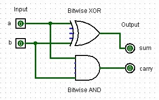
A half-adder is a digital circuit that adds two single binary digits and produces a sum and a carry. The sum is the XOR of the inputs, while the carry is the AND of the inputs.
Truth table for a half-adder:
| Input A | Input B | Sum | Carry |
|---|---|---|---|
| 0 | 0 | 0 | 0 |
| 0 | 1 | 1 | 0 |
| 1 | 0 | 1 | 0 |
| 1 | 1 | 0 | 1 |
 |
|---|
| A half-adder design created in Logisim with two input bits, two output bits, one bitwise XOR and one bitwise AND logic gate. |
module half_adder(
    input a, b,
    output sum, carry
);
    assign sum = a ^ b;
    assign carry = a & b;
endmodule
Let's test this baby to see if it actually does what it is supposed to do. For that, we add a little testbench to our previous code like this
module half_adder(
    input a, b,
    output sum, carry
);
    assign sum = a ^ b;
    assign carry = a & b;
endmodule

// Testbench
module half_adder_tb;
    // Declare signals
    reg a, b;
    wire sum, carry;

    // Instantiate the half adder
    half_adder ha1 (.a(a), .b(b), .sum(sum), .carry(carry));

    // Generate VCD file
    initial begin
        $dumpfile("modules/half_adder.vcd");
        $dumpvars(0, half_adder_tb);

        // Test cases
        a = 0; b = 0; #10;
        a = 0; b = 1; #10;
        a = 1; b = 0; #10;
        a = 1; b = 1; #10;

        $finish;
    end

    // Display results
    initial begin
        $monitor("Time=%0t a=%b b=%b sum=%b carry=%b", $time, a, b, sum, carry);
    end
endmodule
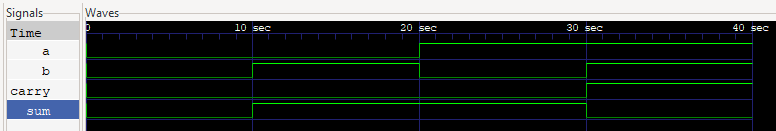
Follow the steps for using GTKWave of the previous chapter and you'll see a return in the terminal and a waveform like this:
VCD info: dumpfile half_adder.vcd opened for output.
Time=0 a=0 b=0 sum=0 carry=0
Time=10 a=0 b=1 sum=1 carry=0
Time=20 a=1 b=0 sum=1 carry=0
Time=30 a=1 b=1 sum=0 carry=1
 |
|---|
GTKWave snapshot of the signals returned from the half_adder.v testbench. |
Does that make sense? Yes! Great. Let's move on to the next module.
Full-Adder
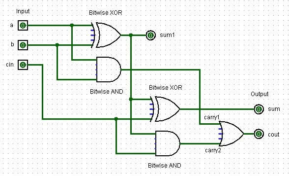
A full-adder adds three single binary digits (two inputs and one carry-in) and produces a sum and a carry-out. It's implemented using two half-adders and an OR gate.
Truth table for a full-adder:
| Input A | Input B | Carry In | Sum | Carry Out |
|---|---|---|---|---|
| 0 | 0 | 0 | 0 | 0 |
| 0 | 0 | 1 | 1 | 0 |
| 0 | 1 | 0 | 1 | 0 |
| 0 | 1 | 1 | 0 | 1 |
| 1 | 0 | 0 | 1 | 0 |
| 1 | 0 | 1 | 0 | 1 |
| 1 | 1 | 0 | 0 | 1 |
| 1 | 1 | 1 | 1 | 1 |
 |
|---|
| A full-adder design created in Logisim with two input signal bits, one control bit (cin), two output bits, one controt output bit (cout), and several XOR, AND and OR logic gates. |
module full_adder(
    input a, b, cin,
    output sum, cout
);
    wire sum1, carry1, carry2;

    half_adder ha1(.a(a), .b(b), .sum(sum1), .carry(carry1));
    half_adder ha2(.a(sum1), .b(cin), .sum(sum), .carry(carry2));

    assign cout = carry1 | carry2;
endmodule
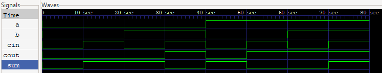
I won't show you the test bench here but you can see it in the modules directory on Github. The results are as expected:
VCD info: dumpfile modules/full_adder.vcd opened for output.
Time=0 a=0 b=0 cin=0 sum=0 cout=0
Time=10 a=0 b=0 cin=1 sum=1 cout=0
Time=20 a=0 b=1 cin=0 sum=1 cout=0
Time=30 a=0 b=1 cin=1 sum=0 cout=1
Time=40 a=1 b=0 cin=0 sum=1 cout=0
Time=50 a=1 b=0 cin=1 sum=0 cout=1
Time=60 a=1 b=1 cin=0 sum=0 cout=1
Time=70 a=1 b=1 cin=1 sum=1 cout=1
 |
|---|
GTKWave snapshot of the signals returned from the full_adder.v testbench. |
Now let's continue with some of the other crucial modules and then we'll create our ALU and test it as well.
Adder
This is a 16-bit adder chaining 16 full-adders without carry-in or carry-out, as per HACK specifications. It's used in the ALU for addition operations. To illustrate the principle of how the half-adders are wired up, below is an image of a 3-bit adder I created in Logisim:
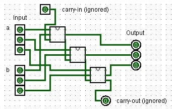 |
|---|
| A 3-bit adder design created in Logisim using full-adders. |
module adder(
    input [15:0] a, b,
    output [15:0] out
);
    wire [16:0] carry;
    assign carry[0] = 1'b0;

    genvar i;
    generate
        for (i = 0; i < 16; i = i + 1) begin : adder_loop
            full_adder fa(
                .a(a[i]),
                .b(b[i]),
                .cin(carry[i]),
                .sum(out[i]),
                .cout(carry[i+1])
            );
        end
    endgenerate
endmodule
Oh, what the heck. You know what? Here is the 16-Bit adder in its full glory as well:
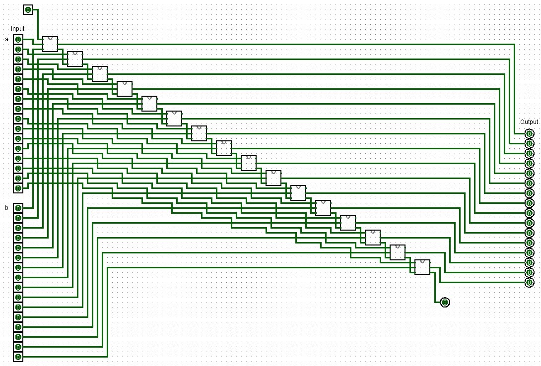 |
|---|
| A 16-bit adder design created in Logisim using full-adders. |
Incrementer
A simple 16-bit incrementer. Here, out = in + 16'd1 assigns the result of in + 16'd1 to the output out where...
in: The 16-bit input vector.16'd1: A 16-bit representation of the decimal number 1. The d indicates that the value is in decimal. It is explicitly specified as 16-bit wide to match the width of the input and output vectors.- And hence
in + 16'd1performs an addition of the input value with the constant value 1.
module incrementer(
    input [15:0] in,
    output [15:0] out
);
    assign out = in + 16'd1;
endmodule
This seems rather simple to implement in Logisim. For example, we may use a 16-Bit adder and simply add 1 with the carry-in bit. Or add one with the second 16-bit number. But this is overly complex as we are essentially wasting 15 input bits and hence also all of the half-adders that would add those two inputs a and b together!
Instead, half-adders to the rescue!
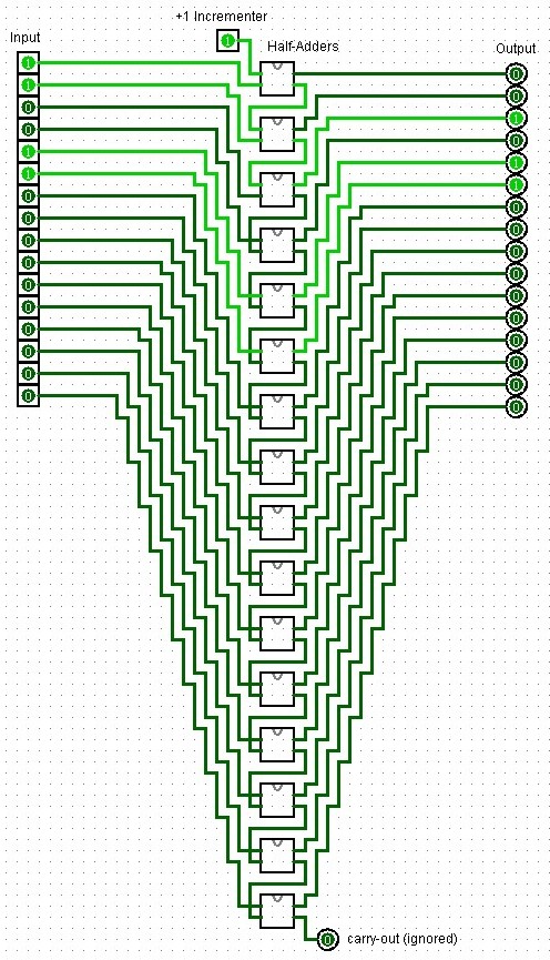 |
|---|
| An incrementer design created in Logisim using half-adders. |
Where before we still had to generate a loop to add together our two 16-Bit numbers together, Verilog simplifies the increment by 1 quite a bit even though we require so many half-adders in our Logisim layout. In Verilog, the high-level abstraction provided by the language allows you to describe the desired behavior of a circuit rather than its specific implementation details, such as using a specific set of half-adders. While structural modeling like I did here in Logisim is important for learning and specific low-level design tasks, behavioral modeling is the preferred approach in most professional design scenarios due to its efficiency and flexibility.
Arithmetic Logic Unit (ALU)
This ALU is specifically designed for the HACK computer and can perform 18 different operations based on the 6 1-bit control bits, which are encoded in the HACK machine language instructions:
zx: Zero the x input
nx: Negate the x input
zy: Zero the y input
ny: Negate the y input
f:  Function select (0 for AND, 1 for ADD)
no: Negate the output
It also has two status outputs:
zr: Set to 1 if the output is zero
ng: Set to 1 if the output is negative (MSB is 1)
The ALU performs operations in stages according to the control bits, allowing for a variety of computations using different combinations of these bits. Here is an implementation in Logisim similar to jbchoinard's sixteen design (GitHub). Instead of using the components we built though, I am using the internal ones in part since their UI is nicer. Sill, you could easily just use the adders we created before.
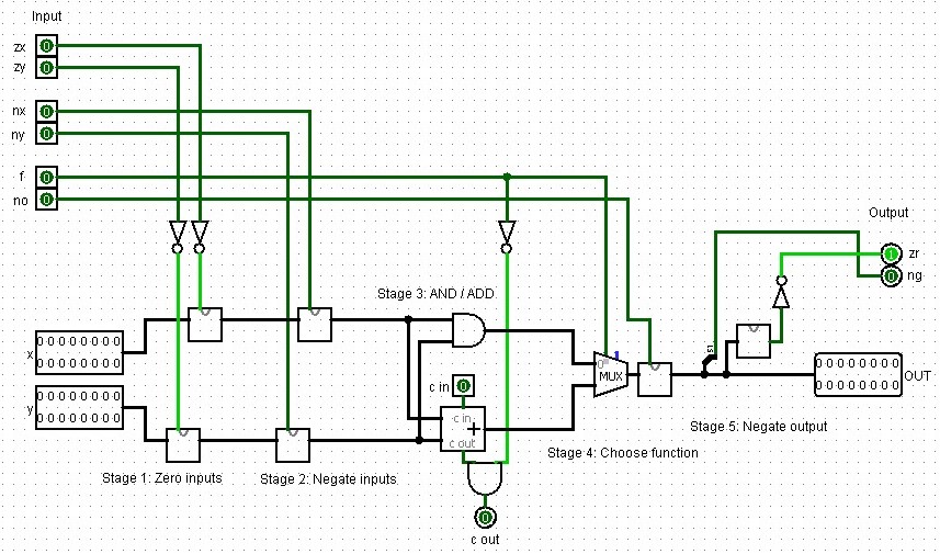 |
|---|
| A full Hack arithmetic logic unit design created in Logisim. |
In Verilog this looks like the code below. I heavily commented this code to explain it:
module alu(
    // This declares the ALU module with its inputs and outputs. The HACK ALU
    // operates on 16-bit numbers (x and y) and has 6 control bits (zx, nx, zy,
    // ny, f, no) that determine its operation.
    // It outputs a 16-bit result (out) and two status flags (zr and ng).
    input [15:0] x, y,              // 16-bit inputs
    input zx, nx, zy, ny, f, no,    // 1-bit inputs
    output [15:0] out,              // 16-bit output
    output zr, ng                   // 1-bit outputs

);
    // These are internal wires used to connect the different stages of the ALU.
    wire [15:0] x1, y1, x2, y2, and_out, add_out, mux_out;

    // Stage 1: Zero inputs
    // If zx is 1, x1 becomes 0, otherwise it's x. Same for y and zy.
    // This implements the "zero" functionality of the HACK ALU.
    assign x1 = zx ? 16'b0 : x;
    assign y1 = zy ? 16'b0 : y;

    // Stage 2: Negate inputs
    // If nx is 1, x2 becomes the bitwise NOT of x1, otherwise it's x1.
    // Same for y2 and ny. This implements the "negate" functionality.
    assign x2 = nx ? ~x1 : x1;
    assign y2 = ny ? ~y1 : y1;

    // Stage 3: AND / ADD
    // This performs both AND and ADD operations on x2 and y2.
    // The HACK ALU always computes both, then selects one based on the f bit.
    assign and_out = x2 & y2;
    adder add(.a(x2), .b(y2), .out(add_out));

    // Stage 4: Choose function
    // If f is 1, the output is the result of addition.
    // If f is 0, it's the result of AND.
    assign mux_out = f ? add_out : and_out;

    // Stage 5: Negate output
    // If no is 1, the output is negated (bitwise NOT).
    assign out = no ? ~mux_out : mux_out;

    // Set zero and negative flags
    // zr is set to 1 if the output is zero.
    // ng is set to 1 if the output is negative (most significant bit is 1).
    assign zr = (out == 16'b0);
    assign ng = out[15];

endmodule
Look at the testbench I wrote in alu.v. Here's what we expect for each case:
x + y: 10 + 5 = 15
x - y: 10 - 5 = 5
y - x: 10 - 5 = 5
x & y: 0b1010101010101010 & 0b1100110011001100 = 0b1000100010001000 (34952)
x | y: 0b1010101010101010 | 0b1100110011001100 = 0b1110111011101110 (61166)
!x: ~0b1010101010101010 = 0b0101010101010101 (21845)
!y: ~0b1010101010101010 = 0b0101010101010101 (21845)
-x: -42 = 65494 (in 16-bit two's complement)
-y: -42 = 65494 (in 16-bit two's complement)
x + 1: 42 + 1 = 43
It returns:
Time=0 x=   10 y=    5 zx=0 nx=0 zy=0 ny=0 f=1 no=0 out=   15 zr=0 ng=0
Time=10 x=   10 y=    5 zx=0 nx=1 zy=0 ny=0 f=1 no=1 out=    5 zr=0 ng=0
Time=20 x=    5 y=   10 zx=0 nx=0 zy=0 ny=1 f=1 no=1 out=    5 zr=0 ng=0
Time=30 x=43690 y=52428 zx=0 nx=0 zy=0 ny=0 f=0 no=0 out=34952 zr=0 ng=1
Time=40 x=43690 y=52428 zx=0 nx=1 zy=0 ny=1 f=0 no=1 out=61166 zr=0 ng=1
Time=50 x=43690 y=    0 zx=0 nx=1 zy=1 ny=0 f=0 no=0 out=    0 zr=1 ng=0
Time=60 x=    0 y=43690 zx=1 nx=0 zy=0 ny=1 f=0 no=0 out=    0 zr=1 ng=0
Time=70 x=   42 y=    0 zx=0 nx=1 zy=1 ny=0 f=1 no=1 out=   42 zr=0 ng=0
Time=80 x=    0 y=   42 zx=1 nx=0 zy=0 ny=1 f=1 no=1 out=   42 zr=0 ng=0
Time=90 x=   42 y=    0 zx=0 nx=1 zy=1 ny=1 f=1 no=1 out=   43 zr=0 ng=0
and
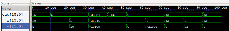 |
|---|
GTKWave snapshot of the signals in signed decimals returned from the alu.v testbench. |
Nice! With that we continue working on the sub-components we need to make sequential changes in our computer, like adding bits to memory and stepping forward in time using a clock.
ALU Operations Table
The HACK ALU's control bits determine which operation is performed. Here are some common operations and their control bit settings:
| Operation | zx | nx | zy | ny | f | no | Description |
|---|---|---|---|---|---|---|---|
| 0 | 1 | 0 | 1 | 0 | 1 | 0 | Constant 0 |
| 1 | 1 | 1 | 1 | 1 | 1 | 1 | Constant 1 |
| -1 | 1 | 1 | 1 | 0 | 1 | 0 | Constant -1 |
| x | 0 | 0 | 1 | 1 | 0 | 0 | Input x |
| y | 1 | 1 | 0 | 0 | 0 | 0 | Input y |
| !x | 0 | 0 | 1 | 1 | 0 | 1 | NOT x |
| !y | 1 | 1 | 0 | 0 | 0 | 1 | NOT y |
| -x | 0 | 0 | 1 | 1 | 1 | 1 | Negate x |
| -y | 1 | 1 | 0 | 0 | 1 | 1 | Negate y |
| x+1 | 0 | 1 | 1 | 1 | 1 | 1 | Increment x |
| y+1 | 1 | 1 | 0 | 1 | 1 | 1 | Increment y |
| x-1 | 0 | 0 | 1 | 1 | 1 | 0 | Decrement x |
| y-1 | 1 | 1 | 0 | 0 | 1 | 0 | Decrement y |
| x+y | 0 | 0 | 0 | 0 | 1 | 0 | Add x and y |
| x-y | 0 | 1 | 0 | 0 | 1 | 1 | Subtract y from x |
| y-x | 0 | 0 | 0 | 1 | 1 | 1 | Subtract x from y |
| x&y | 0 | 0 | 0 | 0 | 0 | 0 | Bitwise AND |
| x | y | 0 | 1 | 0 | 1 | 0 | 1 |